From Figma to interactive UI in ProtoPie
How to test your automotive Figma designs using real data: Guest article by UX designer Bram Bos. Guide on how to bring Figma designs into ProtoPie and connect with relevant vehicle signals.
From Figma to interactive UI in ProtoPie
How to test your automotive Figma designs using real data: Guest article by UX designer Bram Bos. Guide on how to bring Figma designs into ProtoPie and connect with relevant vehicle signals.
"When it comes to designing - and testing - automotive UIs, it's tough to replicate the feeling of real driving conditions. RemotiveLabs has developed something that should alleviate this missing realism".

Bram Bos
UX & product strategy expert, freelance
"When it comes to designing - and testing - automotive UIs, it's tough to replicate the feeling of real driving conditions. RemotiveLabs has developed something that should alleviate this missing realism".
Bram Bos
UX & product strategy expert, freelance
We’re here for you – just email us with any questions you might have!
hello@remotivelabs.comAutomotive UI prototyping with real car data
Nothing beats UX testing on ‘the real thing’. But when you’ve spent any time working in automotive HMI design you know that testing your designs in an actual prototype car is a rare luxury.
Bram Bos is a UX and product strategy expert specializing in human-centered innovation in automotive and beyond. He helps car manufacturers turn strategic visions into user-friendly mobility and HMI solutions. Bram Bos originally published this blog post on Medium.
If you’re lucky, you may have access to a buck setup for judging your UI visuals and ergonomics in a semi-realistic layout.
The lack of realism gets particularly tricky when user testing. As a researcher you’ll have to do a lot of explaining to provide your test users with enough context to understand what they’re looking at (“now imagine you’re driving on the highway at 120km/h”).
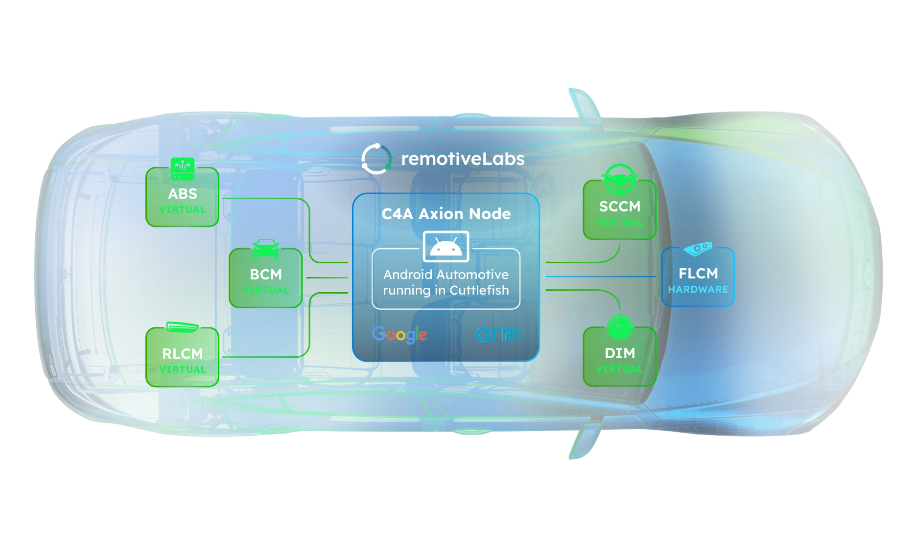
RemotiveLabs has developed something that should alleviate this missing realism. Their tools provide streams of real vehicle data (telemetry, location, etc.) which can help automotive software developers test applications with realistic data in their simulators.
This allows for multiple ways to power simulations:
- choose from a pre-made library of sample recordings,
- upload your own signal data files (e.g., BLF, ASC, or MF4),
- or even connect an actual vehicle for a live data stream to test your HMI designs under real-world conditions.
The case for designers
These tools can also help designers:
- test prototypes of instrument clusters with realistic data(-visualisations)
- bring infotainment mockups to life using vehicle data
- feed live data into a touchscreen duct-taped to any car to test a prototype UI
Curious how easy it is for an automotive UX designer (like myself) to incorporate this into a real-world design prototype, I decided to try and integrate RemotiveLabs’ tools into a typical UI design workflow.
Our UI Experiment: Figma, ProtoPie and RemotiveCloud
Today’s de-facto UI design tool is Figma. Design teams and their stakeholders use it to collaboratively iterate on design proposals.
Ideally, these design iterations also include testing:
- designers need to test their design proposals to evaluate the dynamic aspects of their concepts ‘in motion’
- user researchers need to do usertests with actual users to test intuitiveness, learnability and ergonomic factors.
Unfortunately Figma’s prototyping features are a bit rudimentary and usually not sufficient for automotive purposes. So for interactive prototyping I prefer another tool: ProtoPie.
In the automotive world ProtoPie is a popular prototyping platform because it allows using multiple simultaneous (touch) displays, sensors, and complex conditional logic.
We will need a ProtoPie license that includes ProtoPie Connect (an add-on to ProtoPie which allows prototypes to communicate with external devices and datasources).
Here’s the plan:
We’ll take a Figma design and bring it into ProtoPie to add the interactivity.
Once we have the prototype set up in ProtoPie, we’ll make a connection with RemotiveLabs’ toolset and drive various objects in our UI with streams of vehicle data.
If we can figure out how to do this, the world’s our oyster: we can use real vehicle data as parameters for controlling any aspect of our user interface.
Setting the scene
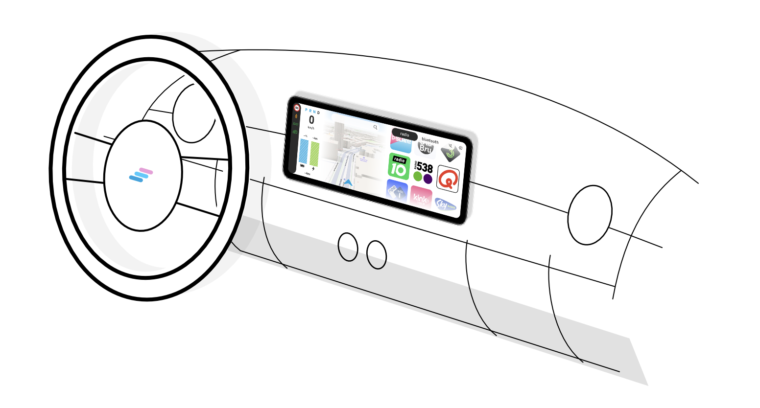
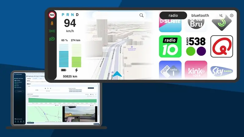
We will be making an infotainment screen for a fictitious urban mini-mobility vehicle. It has a basic central touch screen, which functions as both a simple infotainment screen and as the instrument cluster.
The vehicle is designed for short trips around town (typically < 30 minutes) so functionality-wise we will keep the system simple:
- an instrument cluster with the basic information needed for driving the vehicle
- navigation functionality
- a music section, which offers digital radio and a bluetooth music connection to your phone
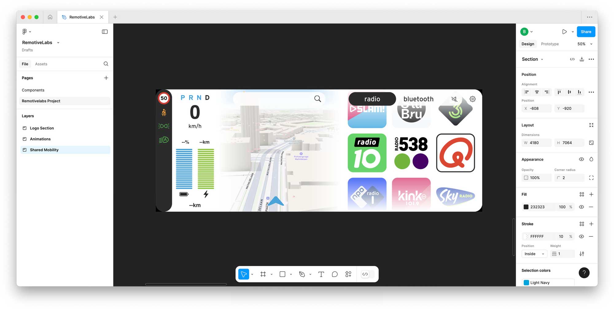
Let’s go: setting up the demo project in Figma
In this experiment we’ll be feeding real vehicle data into various aspects of the instrument cluster section of the screen.
To make this work, we don’t need to do anything special in Figma. We can set up the design as we always do. Needless to say it will make everyone’s lives easier if all layers have meaningful names — but that’s good practice anyway.
From Figma into ProtoPie
Getting your Figma frames into ProtoPie is literally easy as pie. The kind folk at ProtoPie provide a plugin for Figma which let you import frames from Figma and turn them into fully editable ProtoPie “scenes”.
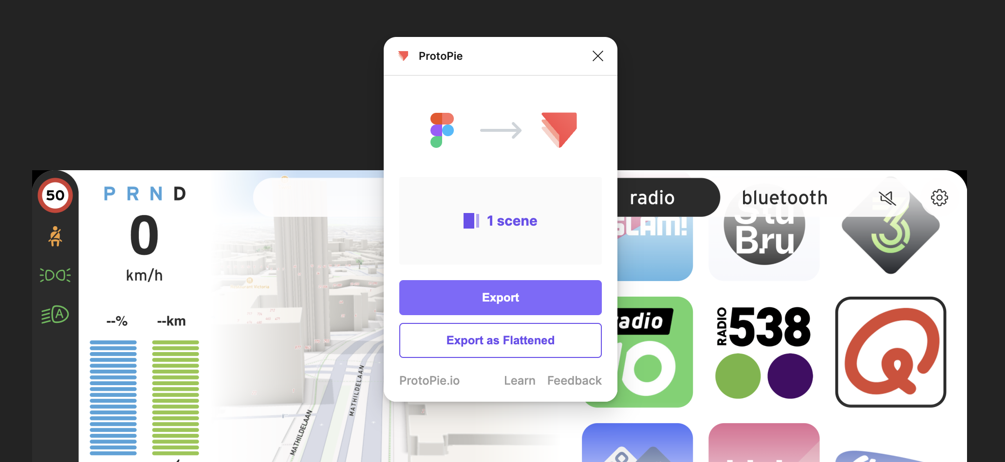
Your Figma design will typically carry over 95% intact. The main things I have seen break in the conversion are:
- gradients
- background blurs (for that popular frosted glass effect)
- image aspects, which can typically be easily corrected in ProtoPie
To bring gradients (e.g. for masks) over from Figma to ProtoPie I recommend copying the gradient layers in Figma as SVG and pasting them in ProtoPie.
Preparing the ProtoPie for realtime data input
The first thing we need to do is to make any layer or object that we want to manipulate ready to receive changes. We do this by selecting the objects and clicking the “Make editable” button for each of them.
Again, double-check that each layer has a meaningful name, because you will need to find them back in a dropdown list.
Once all the layers you want to manipulate using realtime data are editable, it’s time to set up the RemotiveLabs data stream we want to use.
Setting up the RemotiveLabs tools
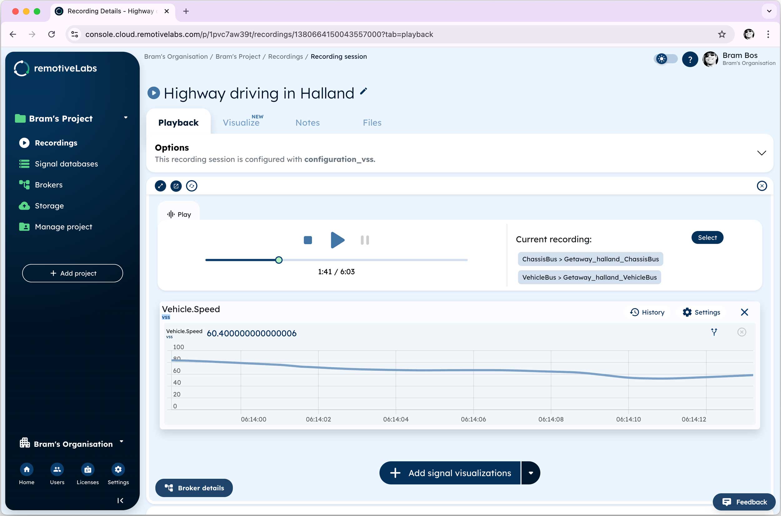
For my experiment I’ve been using the free trial license of RemotiveLabs, which gives access to a number of trial recordings that provide dozens of different variables and signals to feed into our demo.
Sign up for the free tier of RemotiveCloud here: cloud.remotivelabs.com
In their web environment we can cherrypick the signals we want to use in our prototype. And there’s no need to do it all at once, we can always come back later to add or remove signals from our selection.
I prefer to use VSS signals when they’re an option over OEM-specific signals. VSS stands for “Vehicle Signal Specification”, a standardisation protocol for automotive data from Covesa. Read more about it here. The nice thing about VSS is that all signals have meaningful, descriptive names.
I like things that make life easier.
Sometimes it takes a bit of searching for the right signal name, but usually they are quite easy to identify thanks to their naming format:
- Vehicle.Speed
- Vehicle.Powertrain.TractionBattery.StateOfCharge.Displayed
- Vehicle.Powertrain.ElectricMotor.Power
- Vehicle.CurrentLocation.Latitude
- etc.
The signal names are important! We will need to refer to these in our prototype.
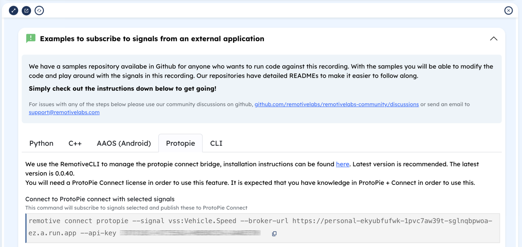
When we’re done we can look up the exact configuration command needed for running our prototype. We’ll paste this command in a terminal window later, so make sure you save it in a location where it can be easily retrieved every time we want to run our prototype.
Feeding the car data into our ProtoPie
There’s one last thing we need to do in ProtoPie before we can run our prototype: make the Pie listen and respond to the VSS signals we selected from the RemotiveCloud stream.
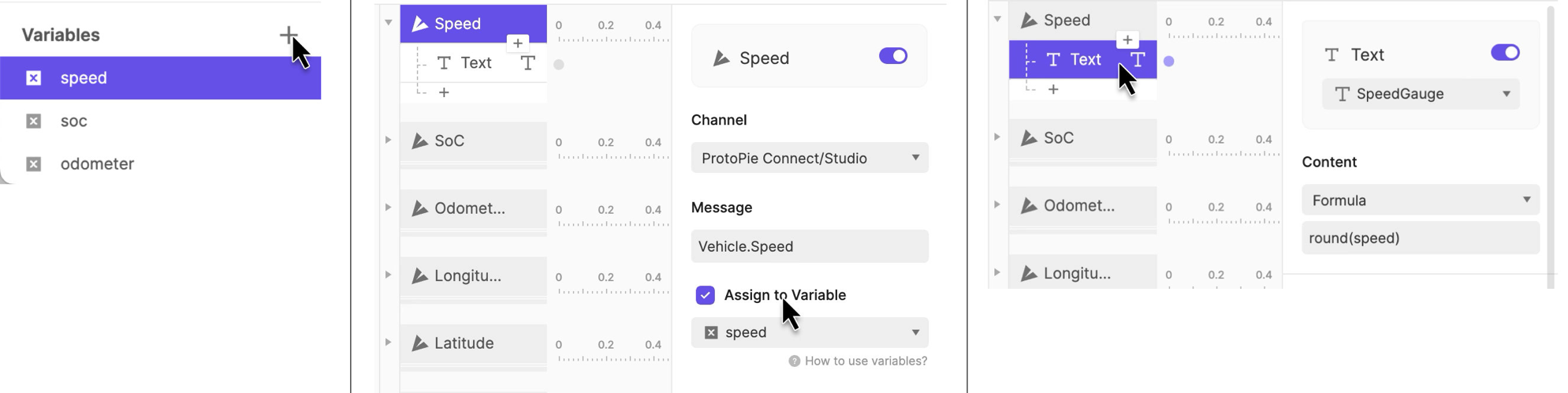
This is a 3-step process in ProtoPie:
- Make a global variable, e.g. a numerical variable named “speed”
- Make a trigger, which will respond when it receives a VSS signal from ProtoPie Connect. It will listen to the name we found in the data stream; e.g. “Vehicle.Speed”
- Add the response: we can put the value we received in a text layer we prepared for this purpose (or change the color of an object, make something [in]visible, etc.).
That’s all. Obviously you can use all of ProtoPie’s extensive logic features to add complex conditional functionality and rich visualisations, way beyond just changing a number on the screen.
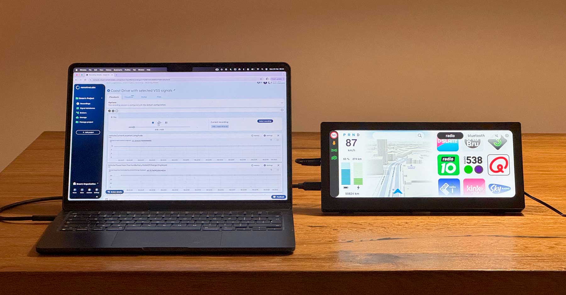
Getting the prototype to run for this first time
We’re now only a few steps away from seeing our prototype run with real data!
1. ProtoPie Connect
Save your Pie (the ProtoPie file) on a local drive, so ProtoPie Connect can get access to it. Then run ProtoPie Connect and locate your local prototype.
Press the little “Display” button next to your imported Pie to open up a ProtoPie demo window. This is the window our interactive prototype will run in.
2. Open RemotiveCloud in a browser window
Go to the browser tab where we configured our data stream. Press play to start sending data. You may need to restart the stream at some point if it runs out before we’re done (depending on the length of the selected stream).
3. Perform some command-line magic in a Terminal window
Next open a terminal window and paste our command line string into it (assuming you have already installed RemotiveCLI. If not, this is a great time for that). RemotiveCLI will serve as our bridge between the data streaming from the RemotiveCloud and our ProtoPie demo.
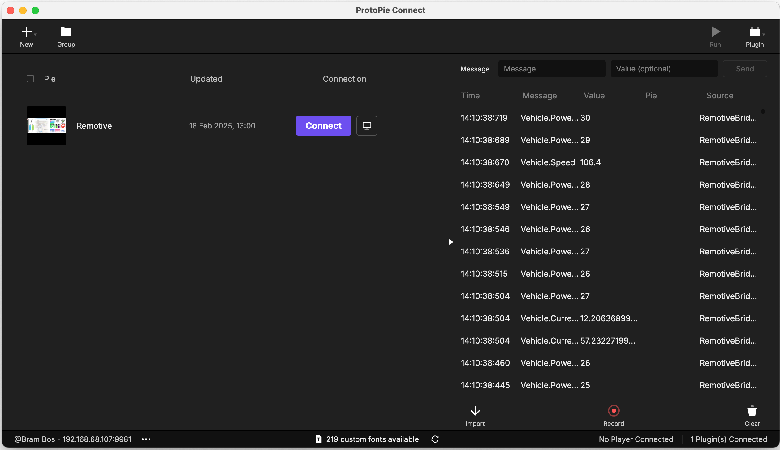
When everything is set up correctly it should automatically detect that both ProtoPie Connect and our RemotiveCloud data stream are in place: you should see all the relevant data points scrolling by in the ProtoPie Connect window.
The UI of your prototype should now be responding to all incoming signals!
Some debugging pointers: if the prototype doesn’t work, check if ProtoPie Connect is receiving signals.
- Yes: the problem is in your ProtoPie prototype.
- No: check if RemotiveCloud is (still) playing back and your RemotiveCLI is running properly (look for error messages in the terminal window).
Next Level Prototyping: maps, location and video streams
RemotiveLabs’ vehicle data streams can include the vehicle’s location data (typically represented by two variables for latitude and longitude).
If you’re up for a bit of a challenge you can use these data points for some advanced prototyping:
- moving maps (which follow the recorded location data of the vehicle)
- linked videostreams (e.g. for simulating parking assists)
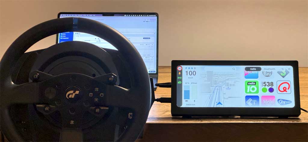
- mixing with input from hardware peripherals, such as steering wheels
To do this you’ll have to use ProtoPie Connect’s advanced features: “Stage View” (to stack web views or live video feeds onto your prototype) and “Plugins” (for cool stuff such as integrating Arduino/Teensy, IFTTT and game controllers).
Those are beyond the scope of this experiment, but it’s good to know it’s possible. And there are plenty of tutorials about these possibilities online.
Now that we know how to access RemotiveLabs data, we can combine all these inputs into highly sophisticated prototypes which will feel much more realistic than the Figma demos we used in the past.
Check out the latest from us

Join the automotive rebels that #getstuffdone with RemotiveLabs!